OnFlight Hub+ sends flight data and analog input measurements to an Appareo RDM-300 through a wired RS-422 connection. The RDM-300 saves this data, and OFH+ can also record to its own microSD card at the same time.
Wiring
OFH+ uses the same three-row, 15-pin female D-sub connector shown on the analog inputs page. Use a matching male connector for the harness. The RDM-300 has a 26-pin high-density female D-sub connector and requires its own matching male harness connector.
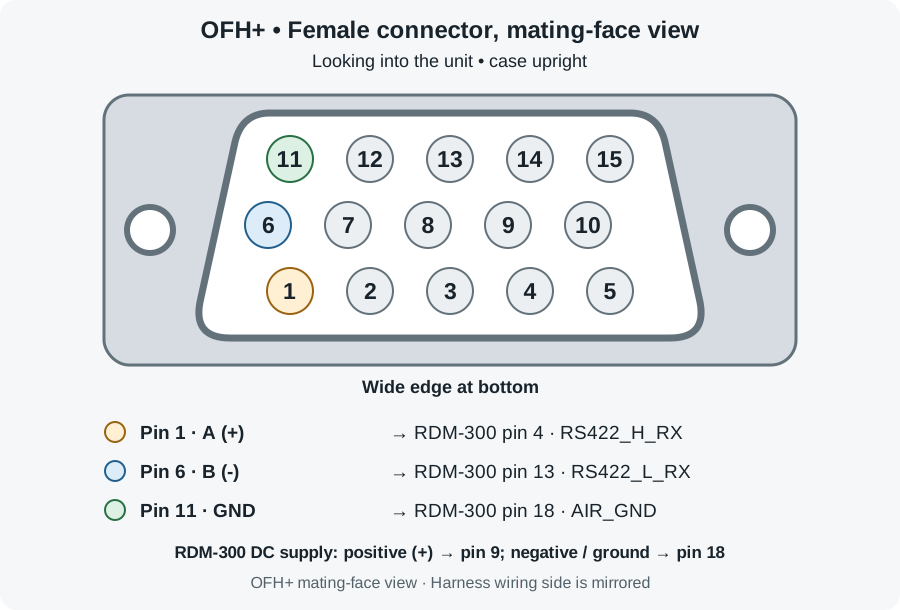
The diagram looks into the connector on OFH+, with the case upright and the wide edge at the bottom. The harness wiring side is the mirror image. Read the pin numbers molded into each connector when assembling the harness.
| OFH+ signal | OFH+ pin | RDM-300 pin | RDM-300 signal |
|---|---|---|---|
| A, differential high (+) | 1 | 4 | RS422_H_RX |
| B, differential low (-) | 6 | 13 | RS422_L_RX |
| Ground | 11 | 18 | AIR_GND |
Connect the pins shown in the table, using a twisted pair for A and B and a separate ground wire between the units. Data flows from OFH+ to the RDM-300; this integration does not require a data connection in the opposite direction.
RDM-300 power connections
Power the RDM-300 from an 8-32.2 V DC supply:
| DC supply connection | RDM-300 pin | Signal |
|---|---|---|
| Positive (+) | 9 | AIR_PWR_IN |
| Negative / ground | 18 | AIR_GND |
The supply negative, RDM-300 pin 18, and OFH+ pin 11 (GND) share a common ground. The RDM-300 needs the separate DC supply shown above; the three wires connecting the units do not power it. Power OFH+ through its normal battery/USB-C arrangement.
The RDM-300 pin assignments and supply range above are from Appareo’s RDM-300 Data Sheet, Rev 1.3, pages 2 and 4. Follow Appareo’s installation requirements for aircraft power protection, cable routing, and termination.
Calibrate the analog control inputs
Calibrate each connected analog input before recording control positions. Follow Analog inputs and calibration to connect the sensors, capture the required calibration points, and verify that the readings respond through the controls’ full travel.
For each calibrated channel, OFH+ sends a normalized control position: 0 to 1 for two-point calibration or −1 to +1 for three-point calibration. If a channel lacks the required calibration points, OFH+ sends that channel’s measured voltage instead. Each channel is handled separately. Verify calibration after changing sensors or linkages.
Recorded fields and rates
OFH+ sends most fields 25 times per second (25 Hz), or once every 0.04 seconds. Satellite navigation (GNSS) fields are sent when the receiver supplies a new sample, normally 5 times per second (5 Hz). Changing the microSD Datalog Rate setting does not change these RDM output rates.
| Data | Rate sent to RDM-300 | Units |
|---|---|---|
| Pitch, roll, true heading | 25 Hz | Degrees |
| Body acceleration X/Y/Z | 25 Hz | g |
| Body angular rate X/Y/Z | 25 Hz | Degrees/second |
| Analog inputs AIN0-AIN3 | 25 Hz | Normalized control position, or volts when calibration is unavailable |
| INS latitude and longitude | 25 Hz | Degrees |
| INS altitude | 25 Hz | Feet above the WGS84 ellipsoid |
| INS north/east/down velocity | 25 Hz | Knots; down is positive |
| Pressure altitude | 25 Hz | Feet, standard pressure |
| UTC date and time | 25 Hz when available | Date and time with 1 microsecond resolution |
| GNSS latitude and longitude | 5 Hz | Degrees |
| GNSS fix and satellite count | 5 Hz | Fix type and number of satellites |
| GNSS altitude | 5 Hz | Feet above the WGS84 ellipsoid |
| GNSS horizontal/vertical accuracy estimates | 5 Hz | Feet |
The inertial navigation system (INS) provides attitude, position, and velocity estimates after navigation initialization. These estimates continue to be sent if INS health becomes degraded. UTC is sent once valid time is available.
UTC includes the date, whole seconds, and a microsecond fraction from 0 to 999,999 within each second. For example, the time can represent 12:34:56.123456. UTC is sent at 25 Hz, with each timestamp encoded to 1 microsecond resolution. This resolution is not a guarantee of timing accuracy.
Record and offload data
Use Appareo RDM Utility to download the recording from the device. This step is required before using OnFlight Data Converter. You do not need the ICD spreadsheet to save a binary recording or export raw ARINC CSV.
- Record data with both units powered and connected.
- Download the recording with Appareo RDM Utility. Save the binary file (
.bin) or export raw ARINC CSV.
Keep the original downloaded file. Both .bin and raw ARINC CSV retain the recorded 25 Hz samples. Choose the raw ARINC CSV export rather than the utility’s summary CSV, which can contain fewer samples.
If you want Appareo RDM Utility itself to export decoded CSV, load the OFH+ ICD spreadsheet before making that export.
Export CSV or MATLAB with OnFlight Data Converter
Use OnFlight Data Converter to turn the downloaded recording into CSV or MATLAB data. It automatically decodes the OFH+ fields, including analog positions, voltages, and GNSS measurements. No ICD spreadsheet is needed.
- Open the binary recording (
.bin) or raw ARINC CSV in OnFlight Data Converter. - Optionally enter Pilot Name, Tail Number, and Aircraft Type. These appear in the first three rows of CSV output. They are omitted from MAT output and do not affect the measurements.
- Choose CSV (25 Hz) for a spreadsheet file or MAT (25 Hz) for MATLAB, then select Convert.
The output is saved beside the input with an _rdm300.csv or _rdm300.mat suffix.
Each output row represents one recorded 25 Hz update. GNSS measurements normally change at 5 Hz; the converter repeats the latest decoded GNSS values in the rows between receiver updates. Those repeated values represent the last received sample.
Measurements that are unavailable are blank in CSV or NaN (unavailable) in MAT. If a new GNSS update is missing part of a coordinate or reports an unavailable measurement, the affected value becomes unavailable. It is not filled from an earlier sample.
Measurement names match the corresponding fields in native OnFlight exports. GNSS altitude and accuracy are in feet, and true heading is shown from 0 to 360 degrees.
See RDM-300 conversion for the complete workflow, CSV/MAT layouts, timing, and output field reference.
Download the ICD for Appareo RDM Utility
The interface control document (ICD) spreadsheet tells Appareo RDM Utility how to interpret the OFH+ data. Load it when exporting decoded CSV with that utility. You can also use it as a reference when writing your own decoder.
Download the OFH+ RDM-300 ICD spreadsheet (.xlsx)
The spreadsheet lists each field’s label, encoding, scale, and units. Keep it with the original recording so you have the definitions used to decode that data.
Some words contain several measurements combined into one integer, called a packed value. Appareo RDM Utility’s decoded export can still contain these packed values. The appendix explains how to extract each measurement; OnFlight Data Converter does this automatically.
Appendix: labels, scaling, and decoding
This appendix is for decoding data with Appareo RDM Utility or your own software. Start with the ICD spreadsheet, then use the instructions below to check data status, apply scaling, and extract measurements from packed values.
OFH+ sends ARINC 429 data words over RS-422 at 230,400 baud, 8 data bits, no parity, and 1 stop bit (8N1). With UTC and 5 Hz GNSS updates, the stream contains 610 words/s, or 3,640 bytes/s including framing. The largest packet is 40 bytes. GNSS latitude, status, and longitude are spread across packets A/B/D; altitude and accuracy follow in the next A, 40 ms after the first packet. Rates and precision are unchanged.
ARINC labels
Each word has a label that identifies its contents. All labels below are written in octal (base 8), including leading zeros where shown.
| Data | Labels |
|---|---|
| Pitch, roll, true heading | 324, 325, 314 |
| Raw body acceleration X/Y/Z | 040, 041, 042 |
| Raw body gyro X/Y/Z | 043, 044, 045 |
| Analog inputs AIN0-AIN3 | 060/061, 062/063, 064/065, 066/067 |
| INS latitude and longitude | 071/072, 073/074 |
| INS altitude | 076 |
| INS north/east/down velocity | 110, 111, 112 |
| Pressure altitude | 203 |
| UTC time and date | 150, 260 |
| UTC microsecond fraction | 070 |
| GNSS latitude and longitude | 050/051, 052/053 |
| GNSS fix and satellite count | 054 |
| GNSS altitude | 057 |
| GNSS horizontal/vertical accuracy estimates | 102 |
Availability and measurement conventions
Check a word’s SSM (sign/status matrix) before decoding its value:
| Word type | SSM for normal data |
|---|---|
| Numeric words, including UTC time and microsecond fraction | 3 |
| UTC date | 0 |
For numeric words, SSM 1 = NCD (no computed data) means the measurement is unavailable. Do not interpret its data bits as a measured zero. A value that cannot be represented in its field, such as an out-of-range value, is also marked NCD. Words with other non-normal status must also be treated as unavailable.
INS fields are unavailable before navigation initialization. After initialization, estimates continue at 25 Hz even if INS health becomes degraded, so their accuracy may deteriorate. Normal SSM means an estimate is available; it does not tell you whether the INS is healthy. The separate INS health flag is recorded in the native OFH+ microSD log and is not included in the RDM stream.
The raw IMU fields are acceleration and angular-rate measurements before INS processing. Sensor calibration, filtering, and the configured mounting rotation have already been applied. For a stationary, level unit aligned with the aircraft axes, body Z acceleration is approximately −1 g. See aircraft axes and mounting orientation.
Numeric scaling and altitude references
For ordinary BNR (binary number representation) numeric fields, the ICD’s Sig Bits and Max columns define the scaling:
value = signed_count * Max / (2 ** sig_bits)
sig_bits is the ICD’s Sig Bits entry, and ** means exponentiation. In this ICD, Sig Bits excludes the sign bit. Using ARINC’s bit numbering from 1 to 32, extract bits (29 − sig_bits) through 29, with bit 29 as the sign bit. Interpret that count as a signed two’s-complement integer, then apply the formula to obtain the value in the ICD’s units.
For example, an acceleration field with 18 significant bits and Max = 16 has a scale of 16 / (2 ** 18) g per count. A signed count of 16384 therefore represents 1 g.
Appareo RDM Utility applies this scaling when producing a decoded export; do not apply it a second time to an already decoded value. Packed fields require the additional steps below. The UTC time and date words use the ICD’s formatting rules instead of this ordinary numeric conversion.
The true-heading word (314) uses signed degrees. To display a heading from 0 to 360 degrees, add 360 to a negative decoded value. For example, −90° becomes 270°.
INS and GNSS altitude use feet above the WGS84 ellipsoid. Pressure altitude uses standard pressure. All three use 0.125 ft resolution, with 20 significant bits and Max = 131072 ft.
UTC date, time, and microseconds
A complete UTC timestamp uses three words from the same 25 Hz update:
| Label | Contents |
|---|---|
| 150 | Hour, minute, and whole seconds |
| 260 | Date |
| 070 | Microseconds within the current second, from 0 to 999,999 |
Label 070 uses 20 significant bits and a BNR scale of 1,048,576, giving 1 microsecond per count. Add the decoded fraction divided by 1,000,000 to the whole seconds. For example, whole seconds 6 and fraction 563864 give 6.563864 seconds.
All three words must be present and have normal status. If one is missing or unavailable, the full timestamp is unavailable; do not combine it with a word from an earlier update.
Analog voltage fallback
OFH+ checks calibration separately for each analog channel. Two-point calibration requires low and high points. Three-point calibration requires low, center, and high points. If any required point is missing, that channel sends measured voltage instead of normalized position.
For example, AIN0 can send a position while AIN1 sends voltage. One word carries both channels, and its label identifies which type of measurement each channel contains. Each update sends one word for AIN0/AIN1 and one for AIN2/AIN3, regardless of calibration availability.
Voltage is encoded in steps of 0.005 V (5 mV). The analog input’s hardware range remains 0–2.048 V. A voltage measurement needs calibration before it can be interpreted as a control position.
Packed-field reference
In the instructions below, packed is the integer obtained after decoding and scaling the word with the ICD. It is not the complete 32-bit ARINC word. Check SSM before extracting any measurements.
Analog channels
Each analog word contains two 9-bit channel codes. Extract the codes as follows:
| Labels | First channel code (lower 9 bits) | Second channel code (upper 9 bits) |
|---|---|---|
| 060, 062, 064, 066 | AIN0 = packed & 511 |
AIN1 = (packed >> 9) & 511 |
| 061, 063, 065, 067 | AIN2 = packed & 511 |
AIN3 = (packed >> 9) & 511 |
The label determines how to convert each code:
| First channel (AIN0 or AIN2) | Second channel (AIN1 or AIN3) | AIN0/1 label | AIN2/3 label |
|---|---|---|---|
| Position | Position | 060 | 061 |
| Voltage | Position | 062 | 063 |
| Position | Voltage | 064 | 065 |
| Voltage | Voltage | 066 | 067 |
For each channel, check for code 511, which means unavailable. For codes 0–510, apply the conversion selected by the label:
| Measurement type | Conversion |
|---|---|
| Normalized position | (code - 255) / 255 |
| Voltage | code * 0.005 volts |
Check the two codes separately. If AIN0 has code 511, AIN1 can still contain a valid measurement.
For example, label 064 with packed = 128255 gives AIN0 code 255 and AIN1 code 250. The label specifies position for AIN0 and voltage for AIN1, so the results are 0.0 and 1.25 V.
If calibration availability changes, the pair’s label changes to identify the new measurement types. Decode the word received in each update using its own label. For example, a change from 062 to 060 means AIN0 has changed from voltage to position while AIN1 continues to send position.
Appareo’s summary CSV may retain a value under the old label after the new label appears. That retained value is an older measurement, not another current reading. Use raw ARINC CSV or the binary recording to identify which word was sent in each update. OnFlight Data Converter handles these label changes automatically.
INS and GNSS latitude and longitude
Each coordinate is split into two 16-bit parts, sent in separate words:
| Coordinate | Lower 16 bits | Upper 16 bits |
|---|---|---|
| INS latitude | 071 | 072 |
| INS longitude | 073 | 074 |
| GNSS latitude | 050 | 051 |
| GNSS longitude | 052 | 053 |
Decode each part as an unsigned integer from 0 to 65,535, then combine them as (high << 16) | low. Interpret the result as a signed 32-bit integer and divide by 10,000,000 to obtain degrees, with 0.0000001 degree resolution.
Both parts of an INS coordinate must come from the same 25 Hz snapshot; GNSS parts must come from the same receiver update. Both words must have normal status. If either part is missing or unavailable, that coordinate is unavailable. For example, a new latitude word 050 cannot be combined with an older word 051 to produce a current latitude.
After decoding a complete GNSS coordinate, OnFlight Data Converter repeats that value in output rows until the next GNSS update.
GNSS fix and satellite count
Label 054 contains the fix type and satellite count:
| Measurement | Decode |
|---|---|
| Fix code | packed & 7 |
| Satellite count | (packed >> 3) & 255 |
Fix codes are 0 = no fix, 2 = 2D, 3 = 3D, 4 = differential, 5 = RTK float, 6 = RTK fixed. For example, packed = 91 means 3D fix and 11 satellites.
GNSS horizontal and vertical accuracy
Label 102 contains two 9-bit accuracy codes:
| Measurement | Extract code | Convert available code to feet |
|---|---|---|
| Horizontal accuracy | packed & 511 |
code * 0.5 |
| Vertical accuracy | (packed >> 9) & 511 |
code * 0.5 |
Codes 0–510 represent 0–255 ft, in steps of 0.5 ft. Code 511 means that accuracy estimate is unavailable. Check the codes separately: an unavailable vertical accuracy estimate does not prevent using a valid horizontal estimate.